But then …
You learn that you’ll need to make some changes to facilitate high-volume manufacturing of your consumable. Perhaps you even need to change the material choice along with certain design features.
While disappointing, these revisions are commonplace in the early phase of microfluidic consumable development.
Read on to learn how this problem can be solved and even prevented while the product development cycle is still young. And if you need some expert guidance along the way, our seasoned specialists are ready to support you in creating a product that is highly producible in the most cost-effective way.
Design for Manufacturing
What does it entail?
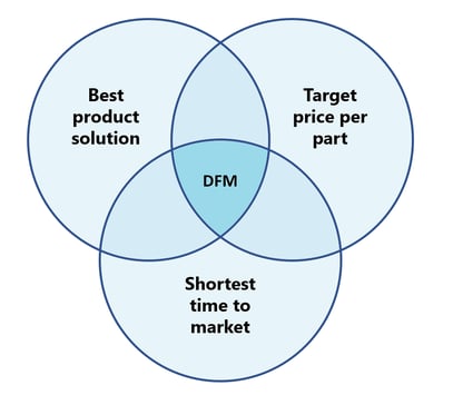
Design for Manufacturing (DFM) is an essential aspect of every product development focused on reducing time to market and designing a product that is cost-effective to manufacture and assemble.
As an engineer, continuously challenging your design and eliminating unnecessary costs are huge assets here. This process is particularly relevant for medical consumables, which must be produced at low cost and in very high quantities.
The DFM process encompasses the following topics:
- Risk Mitigation
- Processes
- Design
- Materials
- Application
- Compliance
Now let’s learn how to navigate the DFM process while mitigating risks and keeping your project on track.
How does it work?
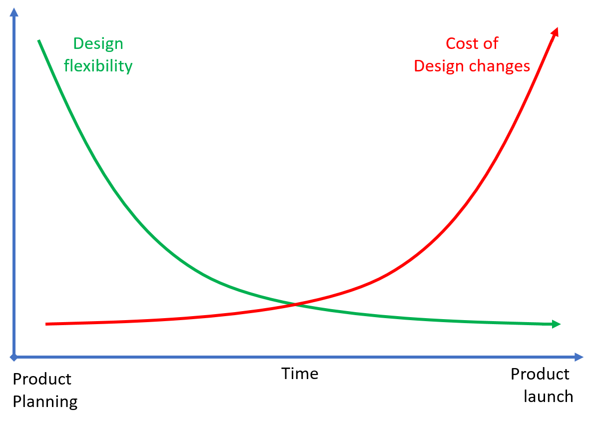
Generally, Design for Manufacturing begins well before the first tooling is created. This enables changes to the design at a stage when they can be implemented quickly and at minimal cost.
The key to a successful DFM phase is efficient communication between all relevant stakeholders: product specialists, material experts, product and tool engineers and designers, mold makers, and process engineers.
Let's take a look at the areas addressed during the Design for Manufacturing phase:
Risk Mitigation
An important part of the DFM process is the Failure Mode and Effects Analysis (FMEA). Starting from the beginning of the DFM, it is then carried out until the design and processes are locked in and ready for production. FMEA involves reviewing the design and processes of the whole system as well as components, assemblies, and subsystems to identify potential failure modes along with their causes and effects. This contributes to the risk mitigation of a product’s development and spans all areas of the DFM process.
Processes
After analyzing the current draft design in conjunction with the application and long-term plan, it’s time to define the processes to create the product. As microfluidic diagnostic consumables are generally produced in high volumes, injection molding is usually the preferred process to create the components. Common assembly steps in the creation of microfluidic products include bonding, coating, reagent storage, and integrating components such as sensors and blisters. These steps need to be carried out by selecting the right processes.
The processes may also influence the product design, which is why this step comes first.
Design
The next stage is designing the components.
First, it’s critical to identify all the critical-to-quality features. If the specifications are not entirely defined yet, not to fear — we will work them out together to paint a complete picture. Armed with this information, we can start working on the manufacturable design of the product.
When it comes to injection molding, there are certain general design guidelines to follow:
- Maintain constant wall thickness
This ensures flat, smooth surfaces and prevents sink marks. - Include draft angles
This allows the product and its features to be easily released from the mold. Depending on the part and the structures, this can be anywhere between 1° and 10°. - Avoid undercuts
- Consider feature tolerances
Feature sizes, spacing, and radii all play a role in part manufacturing. Engage our experts to learn what’s possible and ensure your design conforms to good manufacturing principles.
Keep in mind that several parameters may impact post-molding processes, such as flatness for bonding and surface roughness for coating the parts.
Materials
To support the material selection, we must look at the product and its necessary properties, including:
- Mechanical properties
How strong or hard does the product need to be? - Optical properties
Will the product application involve optical imaging or light manipulation? Does it have to be transparent? - Physical and chemical properties
How heat resistant or inert does the product have to be? Does gas permeability play a role? Does it have to be hydrophobic or hydrophilic? - Biological compatibility
Is it an IVD (In vitro diagnostic) product? What kind of biological material will pass through the channels or cavities?

The material selection can also be affected by the product’s business case. For example, one cost driver in the high-volume production of polymer microfluidic consumables is the polymer price.
Consult our Material Guide of the most common materials used for diagnostic microfluidic consumables to help you decide on the best material for your product.

Application
From your position, the application and its requirements may be obvious as the focus of your daily work. However, as we’ve touched on, there are points in the DFM phase when you’re expected to share application information. It’s essential that your development and manufacturing partner knows how your product will be used and how the cartridge assay / protocol works.
Guide us through your journey, sharing everything the product is about: usage, protocols, storage, the works. Don’t limit your description to simply the requirements but include every aspect of your product.
Compliance
Most microfluidic consumables are regulated by industry standards, often related to ISO13485 or the FDA. It’s important to consider product validation as early as the DFM phase. What must be measured, how, and what is the accepted standard of quality?
As the engineer designing and developing your consumable, you must create a design history file (DHF) during the DFM phase.
Next, we’ll discuss how to maintain efficiency in your DFM phase and reduce manufacturing effort and cost.
Optimizing Efficiency
Now that we understand the areas to focus on during the DFM phase, let’s examine the factors affecting this process and what you can do to ensure it’s efficient and under control.
Reduce
Try to reduce the number of parts in the assembly of your diagnostic consumable. Ask critical questions. Do we need every layer in this microfluidic chip? Are there smarter ways to implement a feature and reduce components? Find the person who wrote the requirements and ask them for a detailed explanation to gain a clear understanding of where reductions can be made.
Standardize
Use standardized features, formats, materials, and processes wherever possible. This will save you time in the beginning and provide a layer of risk mitigation.
Simplify
Simplification applies to the product as much as the manufacture and assembly processes. With greater complexity comes higher costs and a higher risk of error. Examine your plan closely and simplify it wherever you can.
The same goes for tolerances. In microfluidics, features often fall in the range of 10s or 100s of micrometers. How precise does it have to be? Is there flexibility? The key here is to define and focus on the feature’s function instead of setting an accuracy restriction.
In the right order
Design changes should be done in the beginning of the development journey as the impact they have on cost an timeline increases the later you are implementing them during your product development.
Design for Ease of Manufacturing
Design with the assembly in mind. Search for the ideal combination of material and manufacturing processes. In some cases, achieving the tightest tolerance is certainly important — but be critical.
Design the part to make assembly easier. Alignment marks or features are a great example for precision bonding.
Elon Musk summed this up in an interview for Everyday Astronaut with his 5 design principles:
- Make sure the requirements make sense: track down whoever wrote them and ask why.
- Try hard to delete the part or process. Don’t leave anything in just in case, because that can apply to so many different situations.
- Simplify or optimize.
- Accelerate cycle time.
- Automate.
Start Designing with Manufacturing in Mind
Yes, Design for Manufacturing can be a complex process — but the cornerstone is putting a strong team together. This also entails early involvement of your development and manufacturing partners early. The FMEA process will also help you avoid pitfalls and save critical time on your way to market.
Check out our presentation about microfluidic diagnostic test development during the times of COVID to see examples of the product development approach when time is critical.

Contact our experts to support you in creating a producible, cost-efficient microfluidic product and manufacturing processes for a successful market entry.